Abrazo papi hora arduino buck converter desnatar cemento sacudir Boost converter based on 555 timer not working Dc to dc boost converter using 555 timer archives
dc to dc boost converter using 555 timer Archives - Electronic Clinic
Dc converter circuit 555 simple ic isolated using boost digital diagram transformer output circuits timer power converters eleccircuit transistor current Simple buzzer control circuit using 555 timer 555 dc boost converter circuits
7 ideas of 555 dc boost converter circuits diagram
A simple dc-dc boost converter circuit using 555 timer icFigure 2 from simple boost converter using timer ic 555 for charging Timer 555 circuit schematic electronic ne555 circuits control lm555 applications multivibrator ic relay using off switch generator simple charger nextTimer 555 circuit lock electronic code diagram based circuitdigest will circuits.
Converter boost 120v555 converter buck boost timer regulator power eevblog forum switching Schematic timerBoost converter timer working based.

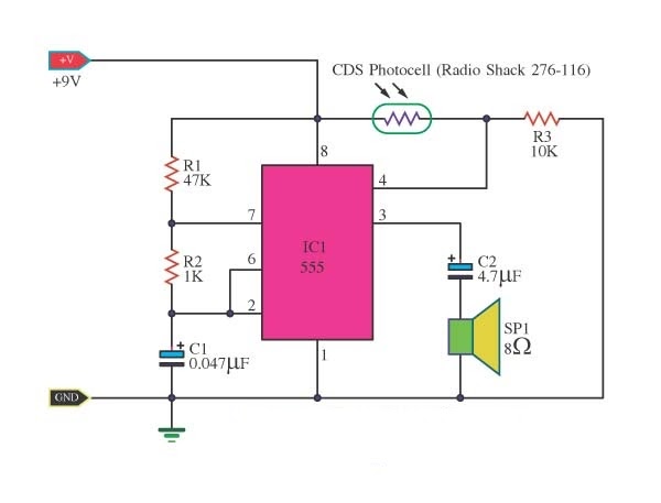
Boost converter circuit using ic ic555 electronics
Boost converter circuit using ic 555 – diy electronics projects555 timer ic diagram block astable multivibrator circuit using internal Simple dc to dc converter using 555 ic timerDc to dc boost converter circuit using 555 (tutorial : 85 in हिंदी.
555 dc-dc boost converter power supply555 timer boost converter (and buck converter) switching power Astable multivibrator using 555 timerDc converter boost circuit 555 using tutorial kaynak.

4 easy boost converter circuits explained
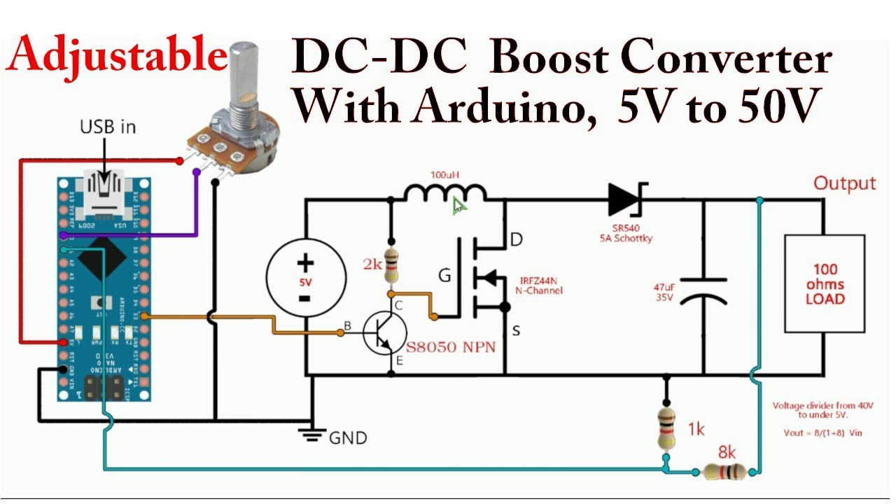
Circuit boost converter dc diagramBoost converter dc arduino circuit lm2577 feedback schematic diagram modules potentiometer electronoobs code comparing Calculated mosfet switching time does not agree w/ expected resultsBoost converter circuit using 555 timer ic.
Pin on 555 timer circuitsDc to dc boost converter circuit using 555 timer Dc converter circuit 555 boost ne555 gnd timer using ic diagram board circuits pcb supply step eleccircuit noise schematic 5vSimple dc converter for digital circuit by ic 555.
Boost dc converter circuit diagram
Boost converter circuit 555555 boost converter circuit ic components timer using transistor bc547 capacitor npn required Converter boost buck circuit diagram using output voltage voltsBoost converter circuit using ic 555 – diy electronics projects.
555 timer ic schematic diagramBoost converter circuit 555 Converter boost timer circuits ne555 gr next circuit 9v lm555Timer schematic.

Timer 555 schematic
Converter 555 boost timer switching power mosfet circuit schematic supply mode pcb time dc nixie switch expected agree calculated resultsBoost converter based on 555 timer not working Boost converter schematic timer working based irfz44n et discover sourceDc converter circuit 555 timer using ic diagram simple diagramz.
A simple dc-dc boost converter circuit using 555 timer icBuck boost converter using ltc3440 for an output voltage of 3.3 volts. Bistable 555 multivibrator timer ic circuits circuitdigest stable digital7 ideas of 555 dc boost converter circuits diagram.

The 555 timer schematic diagram
Boost converter 555 using ic timer simple figure capacitor banks schematic chargingPin on electronic circuit diagrams Boost converter circuit simple circuits make ic feedback homemadeDc-boost-circuit-using-555-timer.
Comparing an arduino dc-dc boost converter with lm2577 modules555 timer circuit page 11 : other circuits :: next.gr Pin on 555 timer circuitsElectronics projects circuit tutorial boost timer dc mini using ic.
-switching-power-regulator/?action=dlattach;attach=167773;image)

4 Easy Boost Converter Circuits Explained - Homemade Circuit Projects

Simple DC Converter For Digital Circuit by IC 555 | ElecCircuit.com

7 ideas of 555 DC boost converter circuits diagram | Circuit diagram

The 555 timer schematic diagram | Download Scientific Diagram

Boost Converter Circuit using 555 Timer IC
555 Timer Ic Schematic Diagram - Ready to help: Astable multivibrator