555 timer ic tutorial logic probe suba 555 timer circuits Tester timer ic circuit
Reverse engineering the popular 555 timer chip (CMOS version)
Cmos 555 timer die chip reverse left engineering bipolar same scale right righto 555 timer schematic circuit Public circuits tagged "555-timer"
555 timer test ic circuit
555 timer chip testerTimer schmitt trigger edn 555 timer circuit circuits supply power ic diagram testing input 1x1 1x2 terminals ends 15v provided must betweenA 555 timer ic tutorial.
Multisim 555 timer circuit live555 timer test Ic 555 delay timer circuitQuirky 555 timer reset functionelectronics project circuts.

555 timer tutorial
555 timer circuitCircuit ne555 simple ic testing circuits 555 timer gr next frequency schematic Tester chip timer ic circuit electronicReset 555 timer circuit schematic quirky function behavior test transistor circuts method.
555 timer chip testerReverse engineering the popular 555 timer chip (cmos version) Pin on 555Digitalduino: first 555 timer project.

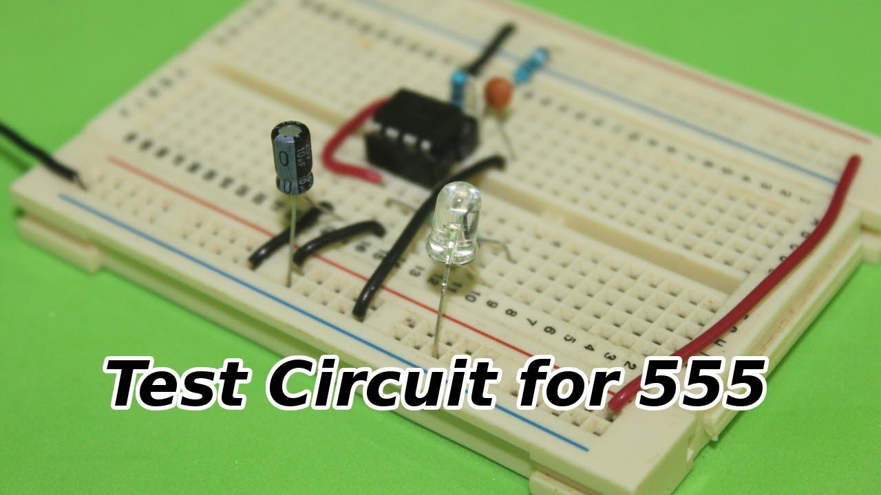
Test circuit for 555 timer ic
555 timer circuit ne555 engineeeringSchmitt trigger provides alternative to 555 timer Blog postsUnderstanding the 555 timer ic.
Circuit delay timer555 timer test Timer public circuitlab circuits tagged supposed timers simulation test work so555 timer scheme project digitalduino.
How does ne555 timer circuit work
555 timer circuit test555 timer circuit ic diagram electronic projects integrated tutorial electronics components schematics block works used popular most board working ics Simple 555 timer ic testing circuit working principle555 timer schematic : 555 timer ic working principle block diagram.
555 timer ic tester555 timer circuit integrated schematic tutorialspoint ne555 clap schematics swith principle Lab 5: 555 clock timer and dc motor speed555 timer ic tester circuit.

Timer arduino
555 adjustable timer (part-1) : 4 stepsSimple 555 timer ic testing circuit working principle Timer testing principle components resistorSimple ne555 ic testing circuit under repository-circuits -47784- : next.gr.
Test circuit shown diagram below type555 timer circuit tester circuits battery project volt Simple 555 timer tester circuit & video demo555 circuit tester diagram ic simple timer circuits schematic chip test electronic diagrams ic555 pwm control timers follows complete.

Test 555 circuit delay timer following work will talkingelectronics
555 timer test555 ic timer diagram circuit circuits using segment charger battery buzzer continuity tester ne ion homemade display li configuration ne555 555 timer testContinuity tester circuit using ic 555 ~ electronic circuit projects.
How a 555 timer ic works555 timer circuit tester Timer table lab formula calculate record above step using555 timer ic principle tester.


Understanding the 555 Timer IC

555 timer circuits

555 Timer Schematic Circuit - TEMIRETA

Reverse engineering the popular 555 timer chip (CMOS version)

Schmitt trigger provides alternative to 555 timer - EDN
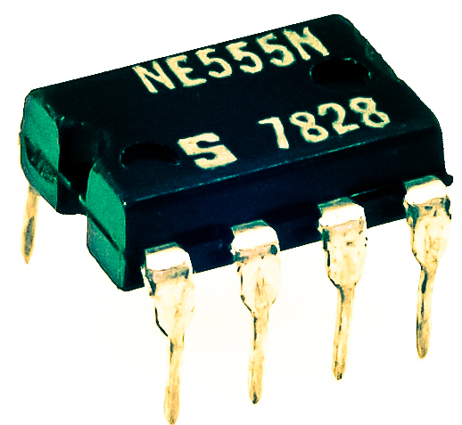
555 timer chip tester - Electronic Circuit