Controller motor dc speed pwm circuit electric brushless mosfet car motors 400hz schematics 3phase digital second depending rds value will Pwm motor speed controller / dc light dimmer Motor controller speed circuit schematic pwm dial make lm555 dc mosfet irf540 supply power makezine electrical need help machine current
Grounding A Dc Motor Circuit Diagram
Pwm mosfet avr atmega atmega8 controller direction atmega32 klucz pnp tranzystor schematics Pwm dc motor controller schematic Pwm motor controller for dc motors and fans
Motor dc pwm circuit speed control 555 ic variable rpm l293d components required
Need help with pwm motor speed controller circuitH-bridge microchip pic microcontroller pwm motor controller Powerful pwm controller for dc motorControl motor pwm schematic.
Electrical – what pwm inputs are needed to drive a 3 phase bldc usingPwm motor dc controller circuit ne555 diagram transistors darlington 555 dimmer led power using transistor voltage generator switch eleccircuit output Pwm dc sluice pulse modulation mdpubPwm tutorial video in high-def.

Pwm bridge motor controller microcontroller microchip pic schematic circuit transistor speed schema project
Pwm dc motor controller schematicTl494 24v controller pwm 20a Pwm 555 timerPwm motor driver, pwm controller dc motor 555 timer ic » timer.
Motor speed circuit controller pwm dc using control ic torque constant single features circuits homemadePwm motor control speed light circuits controller power schematics circuit dc op amp 220v schematic dimmer mosfet pulse width volt Pwm controller for dc motor using 555 timer ic » 555 timer ic hackatronicPwm motor circuit tutorial controller speed 555 groovy diagram projects high electronic width pulse arduino modulation electronics stuff back.

Motor pwm forward controller reverse circuit control dc ic 10a above current supply series maximum used large diagrams
Grounding a dc motor circuit diagramDc motor control pwm with 555 Ftc motor controller circuit diagram555 pwm dc motor controller circuit.
12v-24v pwm motor controller circuit using tl494-irf1405Pwm controller circuit Spectacular dc motor controller schematic schneider motorised mccbDc motor speed controller pwm 0-100% overcurrent protection (second.

Analog lab
Free circuit diagrams: pwm motor controller with forward and reverse24v dc motor controller with 20a shot circuit protection technical 12v-24v pwm motor controller circuit using tl494-irf1405Pwm motor control circuit diagram notes.
Pwm motor controlDanke für deine hilfe fast oxidieren pwm dc motor speed controller Pwm motor schematic feedback controller control begingroupPwm motor speed controller circuit using ic556.

Pwm motor control circuit speed using circuits dc controller diagram power schematic 2009 simple electric loop february closed
555 pwm controller motor timer ic speed simple dc using schematics temperature 100 based circuit electronic electronics nomad ee frequencyAusdauer zugriff sturm pwm dc motor speed controller circuit fülle Pwm schematic control electroschematics hhoDc motor speed control pwm circuit.
Pwm motor speed control circuit with diagram for dc motorPwm timer scienceprog 20a 24v tl494 24vdc pwm eleccircuit motori centralina escPwm motor control circuit – electronic circuit diagram.

Pwm controller power schematic diagram analog circuits illustration integrated electronics
Motor controller dc speed pwm 50a schematic electric control car electronica microcontroller projects using circuit 12v 35v circuits fet currentPwm 555 controller timer circuit circuits diagram projects electronic electronics motor schematics dc solar control board led talkingelectronics arduino light Pwm motor controller schematicPwm controller circuit.
.


Grounding A Dc Motor Circuit Diagram
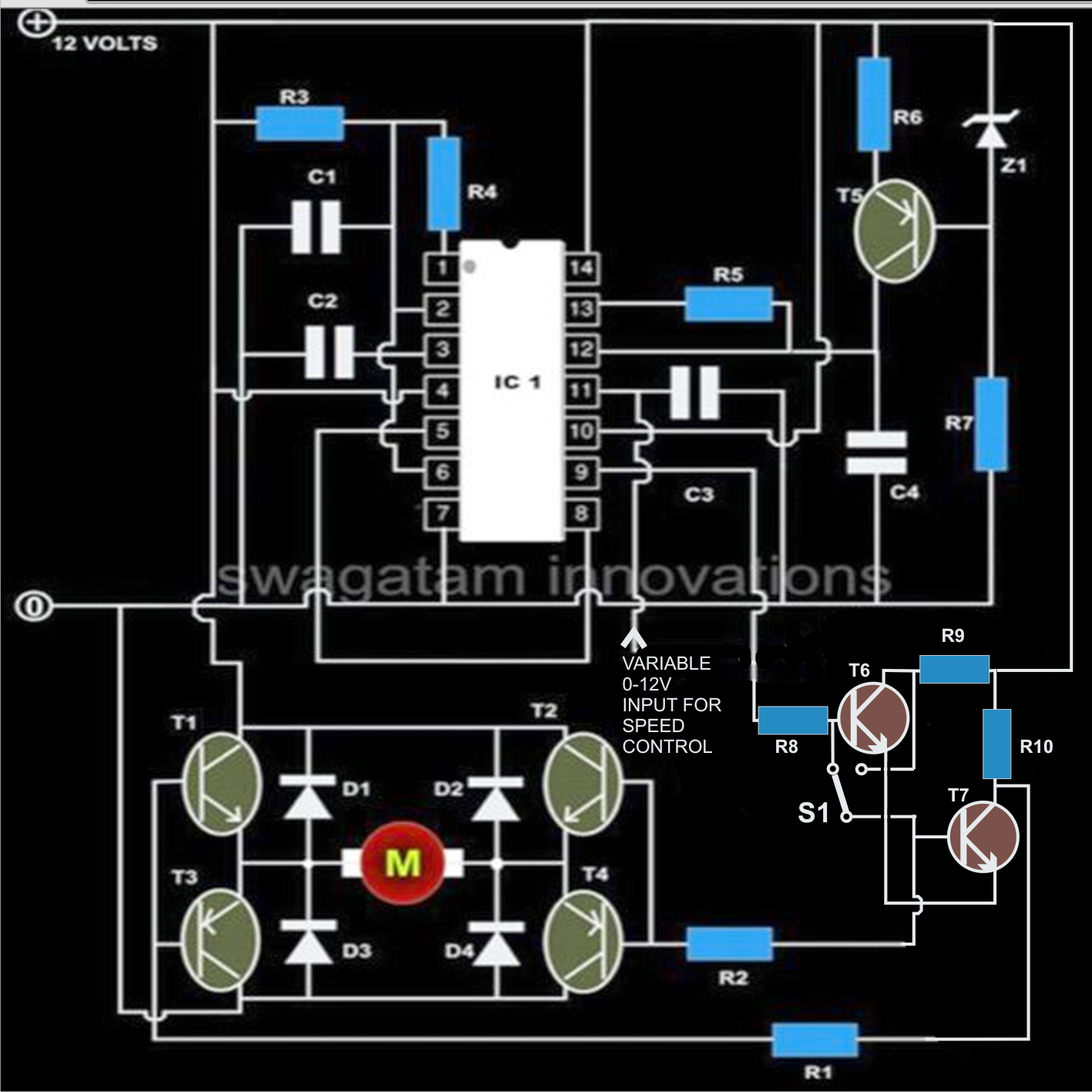
PWM Motor Speed Controller Circuit Using IC556

Ftc Motor Controller Circuit Diagram

Electrical – What PWM inputs are needed to drive a 3 phase BLDC using

24V DC motor controller with 20A Shot Circuit Protection Technical

PWM controller for DC Motor using 555 timer IC » 555 timer IC Hackatronic